trying out the tachometer
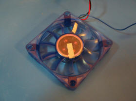
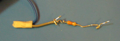
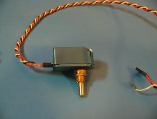
a small 12V fan with hall effect sensor output on blue wire. a series resistor is required to limit the current to the input of the amplifier circuit. (the reflective tape on the fan was used to verify the speed using a laser type tachometer.)
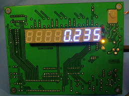
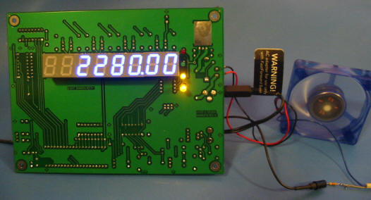
the hall effect sensor is an open collector type that produces two pulses per revolution. in this version of the software, the cpu counts pulses, divides by n (dip-switch setting) and then multiplies by 60. thus, the rpm resolution is 30 rpm. the fan is being powered by only 9V which accounts for the low speed (normally the speed would be closer to 4000 rpm at 12V).
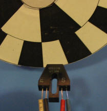
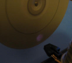
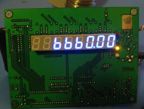
for this test, an old cd covered with this overlay was attached to a variable speed dremel tool (dangerous - keep it under 10000 rpm). the sensor used is a fairchild semi. qrb1114. the ir led is made visible by a digital camera. this overlay produces 10 pulses per revolution so the resolution is 6 rpm.
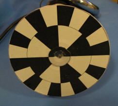

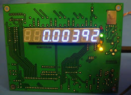
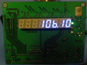
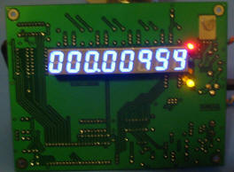
the speed of the dremel is not well regulated. it changes with line conditions and as the motor heats up (made worse by the unbalanced load of the cd). the speed stays around 6600 rpm for this series of pics (rpm, frequency, and period).
due to the current version of the software, if slow speeds are to be measured, a large number of pulses (per revolution) are required. this rotary encoder made by hp was found on ebay for around $25. it produces a quadrature output of 1024 pulses (grey code) per revolution. if only one channel is used, 256 pulses per revolution is the output. the damping mechanism was removed so the encoder can spin freely.
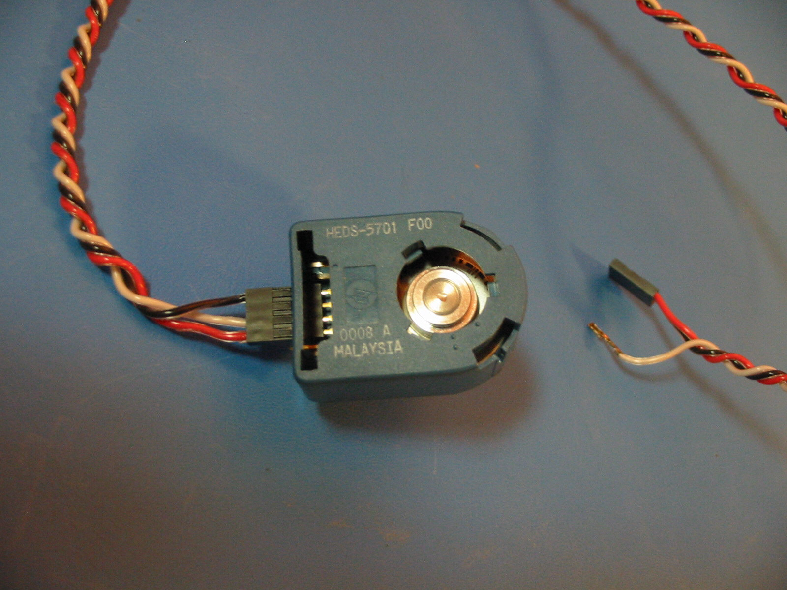
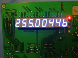
connections to the tachometer board are quiet simple. the power is supplied by the anode and cathode ir led connections and since the output of the encoder is buffered ttl, the first stage of the amplifier circuit can be bypassed by connecting the output to test point 3.
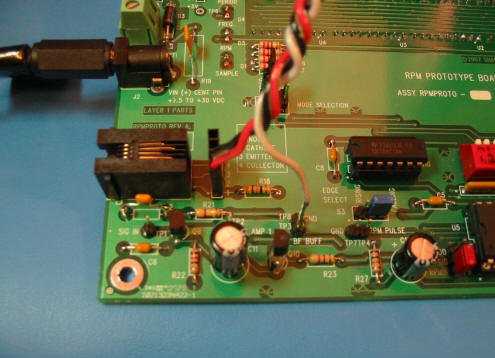
rotating the encoder by hand to produce one pulse per sample period (one second), the following pics show rpm, frequency and period. the software must be modified because the divide by n reads the maximum dipswitch value (255). this is a simple change to the routine that reads the dipswitch value (n + 1). this is a little obvious in the period display (which is the approximate dipswitch value).